Filters to reduce dirty electricity
There are two types of dirt, and filters are only effective against one of them. Filters inserted into wall sockets do not prevent dirt from entering the home; they simply convert it.
The two types of 'dirt' are differential and common-mode, also referred to as symmetrical and asymmetrical interference. Differential mode interference is easy to reduce, whereas reducing common-mode interference is very difficult.
Practice instead of theory
Most people find it very complicated to understand how it
works, so if you already have filters installed in your wall
outlets, it's easier to try it out in practice. As well as a
radio, it is also a good idea to have a magnetic field meter
to check normal magnetic fields. The starting point is our
page about detecting dirty electricity and a testing set up
as described.

Our test results
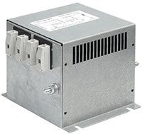
We tested two meters, one of the radios and an electromagnetic interference (EMI) line filter, which must be installed by an electrician, all of which are described on the 'Test for dirty electricity' page. The testing setup was as shown in the figure above. The test was performed without a load, which may have affected the outcome.
Meters vs. radio |
||
| No
filter |
After filter |
|
|---|---|---|
| Stetzer |
1700 |
60 |
| Alpha
Lab |
200 |
13 |
| Radio |
Noise |
No change |
Filters are effective against
differential mode interference, but not common mode
interference. The radio reveals this.
How do the filters work?
There are two fundamental principles for reducing interference.
The differential mode interference

The interference pattern on the two conductors of a cable is more or less mirrored by the pattern on the other conductor of the same cable. To cancel them out they need to come in contact with each other. The result of a positive voltage and an equal but negative voltage is zero voltage.
This connection can easily be made using a capacitor. This is represented by two thick lines in circuit diagrams. The capacitor acts as a solid conductor to the interference. Voltage drives electric current which starts to flow through the capacitor. The voltage across the capacitor and the two conductors drops to almost zero. Has the problem been resolved? No.
The same current that flows through the capacitor also flows through the conductors, creating increased magnetic fields along the cable. Voltage interference is now replaced with magnetic interference.
The common mode interference
The interference patterns on the two conductors within a cable are similar, as are the similar positive or negative voltages on each conductor. There is no mirror pattern on the other conductor to cancel the interference out.
The method of attenuating common mode interference involves choking it by allowing its energy to build up a magnetic field in magnetic material using an electric coil. As long as the magnetic field is increasing, the interference cannot pass through. A coil with that function is called a choke. Sadly, the truth is that a choke is not an effective way of attenuating common-mode interference, and there is no other method. A choke is shown in different ways in circuit diagrams.

Conclusion
Dirty electricity is a problem that is difficult to solve once it has occurred. Common mode interference is difficult to mitigate because simple methods are ineffective. Installing capacitors as 'filters' in wall sockets merely shifts the problem from electric fields to magnetic fields within the home. However, this outcome can be avoided by placing a filter where the electricity enters the house or further away, if it is possible to relocate the electricity meter.
In Sweden, the cables up to the electricity meter and the meter itself are owned by the electricity network company, so approval must be obtained from them to relocate the meter. The cables after the electricity meter are owned by the property owner, who can install a line filter at the desired location. This is a job for an electrician.
Test for dirty electricity using radio and meters.
